The regulation of the CO2 fleet targets of 95 g/km from 2020 for passenger car manufacturers is already well known. However, also with commercial vehicles a reduction of CO2 emissions by 30 % by 2030 from the basis year 2019 has been legally laid down. The corresponding CO2 limit value is calculated EU-wide with the tool VECTO (Vehicle Energy Consumption Calculation TooI), which was developed at the Institute of Internal Combustion Engines and Thermodynamics. Every newly registered commercial vehicle will therefore have assigned a CO2 value. According to that, every manufacturer is obliged to implement efficiency enhancing measures that have a high potential, on the one hand, and are accepted by the costumer (freight companies, etc.) on the other hand.
In order to emulate the passenger car sector, first steps led to an introduction of fully electric vehicles like the MAN eTruck. Regarding the broad spectrum of commercial vehicles, a differentiation in the application of vehicles and a validation on a reasonable degree of electrification has to be performed. With a travelled distance of 700 km per day, the range issue is generally more pronounced here than with passenger cars. Accordingly, the current share of 98 % diesel engines in commercial vehicles in the EU will not change substantially, whereas the on-board electrical system and the share of electric components on and around the internal combustion engine will indeed be adapted.
Currently a voltage of 24 Vis used in the commercial vehicle on-board electrical system. The capacity of the electrical system and, consequently, the maximum stationary power is limited through the critical current values. Therefore, a higher voltage level leads to higher transmissible power as well as more flexibility in the operating range. However, the operating voltage of 48 V is not arbitrary, but derived from the safety limit of 60 V, which would imply contact protection. So it is possible to integrate auxiliaries with a higher power consumption in the electrical system, and an application in commercial vehicles is now feasible in the first place.
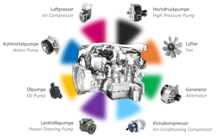
With respect to this, a six cylinder in-line heavy-duty diesel engine of the 12 L class with 324 kW rated power was investigated on an engine test bench at the Institute of Internal Combustion Engines and Thermodynamics. The auxiliaries of such an engine are depicted in Figure 1.
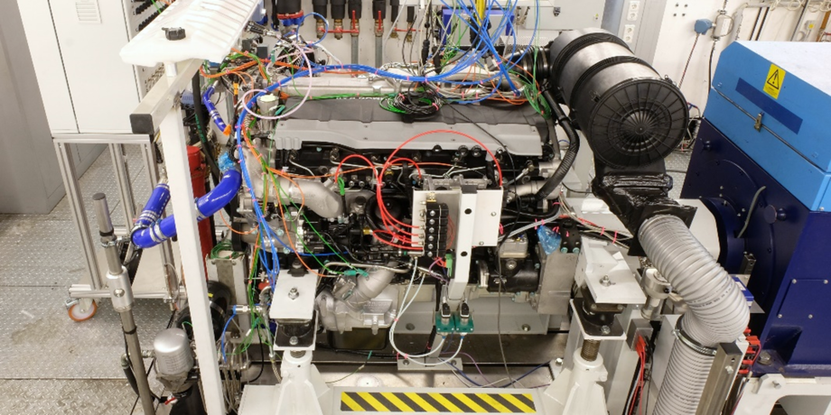
The power consumption of those components are implicitly included in the friction losses of the internal combustion engine. In order to be able to measure the power of selected components in engine operation accurately and perform a thermodynamic loss analysis, the engine was equipped with six cylinder pressure sensors. The difference of indicated and effective power results in the engine friction. Figure 2 shows the test bench setup for the performed measurements.

Figure 1: Auxiliaries in a commercial vehicle diesel engine.
The potential for an increase in efficiency and therefore CO2 savings lies in the decoupling of the auxiliaries from the engine speed. According to that, the key element is the demand-controlled operation of the components. Electrical auxiliaries thereby have the highest grade in flexibility. While in passenger cars there are already products in series application, commercial vehicles still use a rigid drive through belt or spur wheel. Due to the higher transmissible power in the 48 V network, auxiliaries can also be substituted by electrical components now.
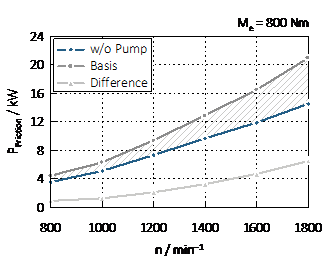
Regarding the coolant pump, the influence of a demand-controlled operation on the efficiency of the engine becomes clear. Through a fired strip-down measurement, in which the auxiliaries are gradually removed, the power consumption of the mechanical coolant pump could be determined. The results are depicted in Figure 3, where the hatched area shows the difference.

Friction share of mechanical coolant pump over speed.
Hence, the correlation to the engine speed can be derived. The volume flow rate, which the mechanical pump delivers, stays constant over load. This is where the original problem is coming from. Not only in idle mode, but also at full load, the coolant pump needs the same drive power, even though the cooling demand is significantly lower at idle. To meet this requirement, electric water pumps (EWP) have been applied.
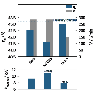
The EWP were supplied with 48 V and had to be arranged in parallel due to the high flow rate of a commercial vehicle engine. Firstly, as mentioned above, the friction level of the basis setup in a representative load point of a constant drive on the highway with a fully laden vehicle was determined (see Figure 4).

Influence of a reduction in coolant flow on the brake thermal efficiency in the highway load point.
If the series volume flow rate is provided by an EWP, no benefit in the brake thermal efficiency η_e is gained, caused by the higher friction power P_Friction. On the basis of that, the volume flow rate was reduced by half. Consequently, the friction power could be reduced by 16 %, whereby an efficiency enhancement of 0.5 % Pt. was determined. This corresponds to CO2 savings of 1.2 %. Other potentials, which are gained with the application of EWP, are found in engine warm-up and charge air cooling. With the reduction of the coolant volume flow rate up to pump standstill, benefits in cold-start can be realized. This is especially interesting with regard to future test cycles, which will include the cold-start phase more.
From these investigations it can be derived that an electrification of the auxiliaries alone will not make a CO2 reduction of 30 % by 2030 feasible. However, it can be stated that with the introduction of the 48 V on-board electrical system, the implementation of other technologies, such as waste heat recovery as well as brake energy recuperation and further hybrid functionalities, are realizable. Furthermore, it shows that the potential of internal combustion engines is far from exhausted and electrification can be utilized as an additional degree of freedom.
