Transonic Test Turbine Facility (TTTF)
Within the research programs at the Institute for Thermal Turbomachinery and Machine Dynamics, in 1995 design and building of a transonic test turbine facility was started. In November 1999 the turbine test facility was run for the first time. This facility is driven by a compressor station of 3 MW power and allows testing of transonic gas turbine stages in full flow similarity. The test stand gives access of conventional pressure and temperature probes as well as of optical measurement devices such as Laser-Doppler-Velocimetry (LDV) and Particle-Image-Velocimetry (PIV) systems. Changing demands from research projects resulted in several modifications. Since the commissioning hundreds of hours of test runs with many different transonic turbine stages were performed.
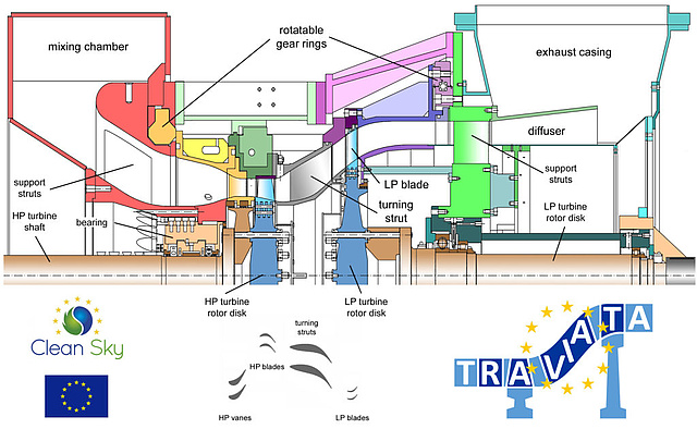
Within the EU Project DREAM the Facility was upgraded to a two-shaft two-stage test turbine for testing of intermediate turbine structures of modern high-bypass-ratio turbofan engines.


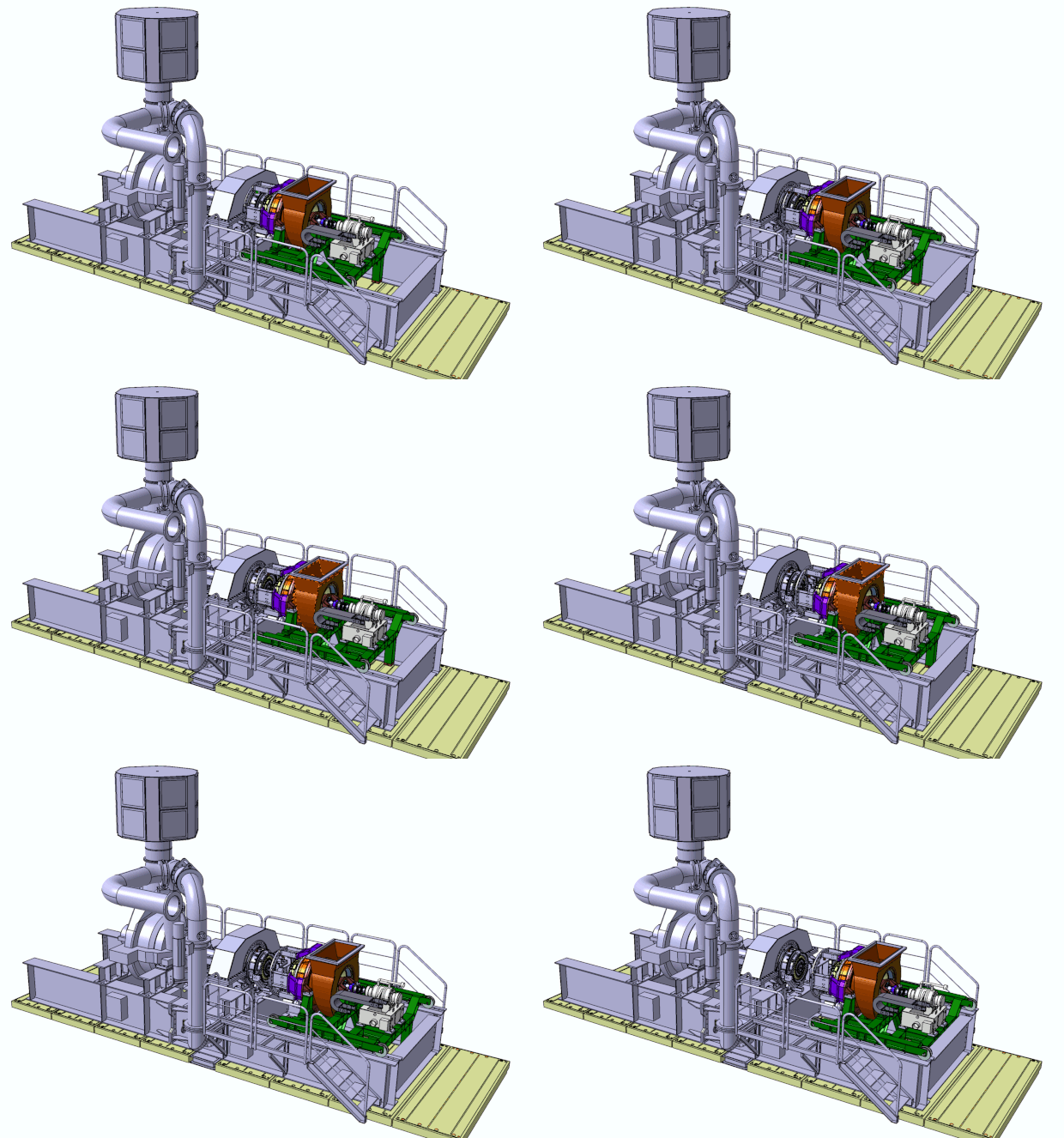
The following picture shows the main components of the facility. Pressurized air, delivered by a separate electrically driven compressor station with 3 MW power, is fed to the HP turbine stage to be tested. The test turbine drives the brake compressor shown at left. The pressurized air from the brake compressor can be added to the air from the compressor station in a mixing chamber. The air from the compressor station may be cooled to about 50 °C, whereas the temperature of the brake compressor air depends on the pressure ratio. After the HTP the air is transferred by the intermediate turbine duct to the LP turbine at larger radius. This second LP shaft is controlled by a water brake of max. 700 kW power.
The exhaust air from the turbine normally flows through an exhaust line directly to the silencers in the exhaust tower. A suction blower driven by a 700 kW engine (previously a helicopter engine) allows the control of the pressure in the exhaust line in order to reduce the turbine back pressure and thus increase the turbine overall pressure ratio.
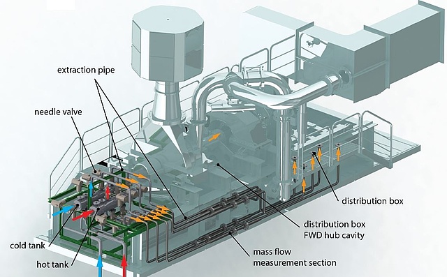
Within the EU Project ENOVAL a Secondary Air System was included in order to provide engine realistic cavity and purge flows in the HPT as well as in the LPT.

Institute of Thermal Turbomachinery and Machine Dynamics
Graz University of Technology
Inffeldgasse 25/A
A-8010 Graz
Tel: +43 (0)316 873 - 7226
Fax: +43 (0)316 873 - 107226
ttm@tugraz.at
