Turbomachinery laboratory: efficient and aerodynamic aircraft engines
Emil Göttlich's work flies in the heavens. Ironically, however, his area of responsibility extends for two stories below ground and is dark and dangerous. The turbomachinery laboratory of the Institute of Thermal Turbomachinery and Machine Dynamics, whose laboratory manager is Göttlich, covers an area of approximately 1,500 square meters. This is where the aerodynamics of aircraft turbine components is tested and improved. “You don't see these improvements at first glance," explains Göttlich. "In some cases, it involves changes of a few millimeters in geometry, which can save a lot of money." Savings in air traffic mean above all savings in kerosene consumption and thus not only lower costs for the airlines, but above all fewer environmentally harmful emissions.
Incidentally, according to Göttlich, kerosene will continue to be the most important aircraft fuel in the future: "There is currently no serious alternative. But kerosene will no longer be obtained from fossil raw materials, but can be synthesized from water and carbon dioxide, for example, using green energy. The carbon emissions that are subsequently released during combustion are also green if the kerosene is produced using carbon dioxide previously separated from flue gas or from the atmosphere. So you could fly with virtually no emissions."

Emil Göttlich heads the turbomachinery laboratory at Inffeldgasse, Graz. © Lunghammer – TU Graz
An aircraft engine consists of several components. In short, it works by having several axial-flow impellers transporting air through the engine. At the very front is the fan – a large blower wheel. It pushes air through the engine and some of it also into the compressor stages, where it is compressed and thus also heated by several, ever-smaller impellers. The compressed air is mixed with kerosene in the combustion chamber and ignited. The hot combustion products are then passed through several turbines that drive the compressor stages. Finally, the air comes out of the engine faster than it goes in at the front and thus propels the aircraft. Most of the air passes through the engine only through the fan and the bypass duct, which runs around the turbine and combustion chamber duct, and remains cold. The turbine center frame is located after the combustion chamber and between high- and low-pressure turbines and is therefore subject to high thermal loads.
Play video
But the fuel used to operate the turbine is basically irrelevant to Göttlich and his research group from a research perspective; – the object of their research does not change even with a different fuel. “We’re not concerned with the turbine combustion chamber, but with what comes after it." This is the so-called transition duct or turbine center frame (TCF for short). It is located between the high-pressure (HPT) and low-pressure turbine (LPT), i.e. after the combustion chamber, and is thus one of the hot-gas path parts of the engine. In order to intensively test the aerodynamics of this part of the engine, the Institute operates several test rigs. The core of the Institute is the large test turbine which is driven by the 3-megawatt compressor plant located deep below ground in the second basement and which makes the Institute currently unique on the European research landscape. Unique not because of the turbine itself, but because of the special test setup – a combination of a test turbine and a brake compressor driven directly by the turbine – which the Institute has developed and which thus enables much larger air volumes to be passed through the test setup.
The transition duct of an aircraft engine is exposed to enormous temperatures – not the 1,500° Celsius that prevails after the combustion chamber, but still a considerable 1,000° Celsius. Temperatures that represent a massive obstacle for experiments, as Göttlich explains: "Many necessary measuring techniques can no longer be used at such high temperatures." However, the Institute has succeeded in mapping the flow conditions that prevail at these enormously high temperatures and at lower temperatures and is thus able to conduct experiments under real conditions but at 60° to 80° Celsius, which is suitable for experiments. "We use speed and pressure profiles as well as Mach number similarity for this purpose, so we have the same effects that would occur in a real jet engine. The transition duct thinks it's in a real engine." In the future, we would also like to simulate the temperature gradients – burners which are arranged around the combustion chamber produce hot layers in which the air is even hotter than in the ambient air – if not in reality, then at least in simulation. "In addition to the wind tunnels, we also operate a test rig on which the combustion chamber itself is examined – the hot-flow test facility. There would thus be the necessary infrastructure to heat the air and to feed the layers selectively into the wind tunnel or turbine – but of course again at temperatures lower than in a real engine," says Göttlich. But that is still a dream of the future.
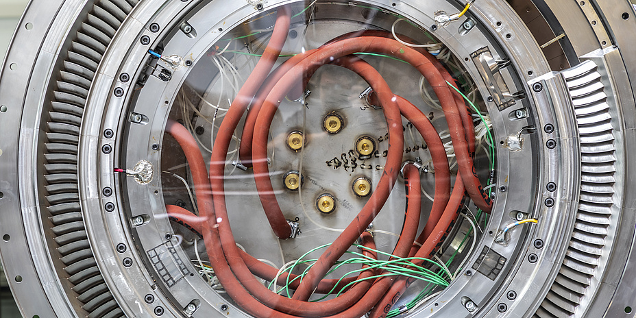
The Transonic Test Turbine Facility is the institute's large test turbine, and can even be used to realize air velocities in the supersonic range. The test rig went into operation in 1999 and consists of a high-pressure turbine stage, a turbine center frame and a low-pressure turbine stage, thus reproducing the aircraft engine after the combustion chamber. However, the tests are not carried out at around 1,000° Celsius, as would be the case in a conventional aircraft engine, but at around 60° to 80° Celsius. Only in this way can a large part of the measuring methods be used at all.

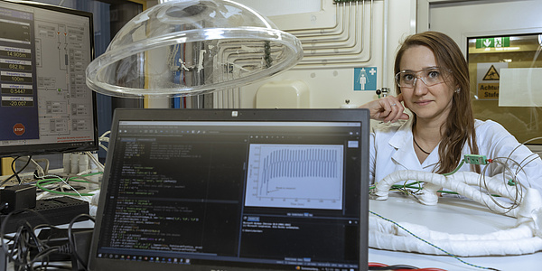
In the transonic test turbine facility the inflow conditions in an aircraft engine can be realistically simulated from take-off to landing at around 60° to 80° Celsius. © Lunghammer – TU Graz
Much more up-to-date at the moment is a new wind tunnel that extends over three floors and is currently being prepared for the first tests. This test rig is a gift from the long-standing research partner General Electric, a well-known US American group. The new test rig is primarily used for preliminary tests on blade cascades – a blade cascade is several blades placed side by side on a round turbine, for example, which transport air. In these preliminary tests, the most promising geometries are determined and test specimens are selected for the more expensive and much more complex tests on the Institute's own test turbine. "At the turbine test rig, bullet-proof glass separates the test room from our observation station and the test rig is surrounded by a thick steel containment," describes Göttlich. "Tests are carried out here using mobile – i.e. rotating and moving – parts, and when everything is in full operation, special safety requirements and access rules apply in the laboratory." Only non-mobile parts are tested on the new sector cascade test rig. "Here we can install a quarter sector of the blade grid directly into the test rig and let air that is not moved by a turbine flow statically through it," explains Göttlich. The inflow conditions behind a turbine are simulated with specially manufactured metal screens. For this reason, in the future and after comprehensive training, students at the Institute itself can use this test rig – something which leads to an immense increase in productivity. Of particular interest to the research partners are the pressure loss in the transition duct and the quality of the flow which subsequently meets the turbine stage.
The test rig itself consists of an air compressor deep in the first basement and is therefore a self-sufficient system. All other test rigs at the institute get their compressed air from a large, common compressor unit (by the way, the largest mechanical engineering plant at TU Graz). It draws in air from the outside, compresses it and directs it into a pipe system that extends from the first basement floor to the first floor and is then routed via a mass flow measurement and a heat exchanger back down to the ground floor to the actual experimental unit. Here the test specimen is installed and the compressed air flows through it. "GE used to do this preliminary work itself, but today the entire experimental setup is in our hands. It makes you proud that such an impressive company as GE has its components tested and optimized in modest Graz," adds Göttlich.

The new wind tunnel at the Institute is primarily intended for preliminary tests in which promising geometries are selected. © Lunghammer – TU Graz
Various test rigs for various test requirements
In addition to the test turbine and the new wind tunnel, the Institute operates a ring grid cascade – a special version of the transonic cascade which also works with static inflow, but needs the same amount of air and thus the same amount of electricity as the experimental turbine. With a second test turbine – the subsonic test turbine facility – the stage at the very end of the engine is checked not only for aerodynamics but also for acoustics and blade vibrations. And in the already mentioned hot-flow test facility, the combustion chamber of the engine is also examined.
The fact that the majority of the test rigs are located underground or in windowless test halls does not bother the researchers at all. Daylight is absent during the testing campaigns anyway. In principle, the tests are carried out at night, except for the new sector cascade test rig. This is because the wind tunnels have such a high power requirement that the power grid of TU Graz would have difficulty coping with the additional load in normal daily operation. At peak times, the Institute's turbine tests would bring about a total demand of over 6 megawatts. In comparison, the entire rest of TU Graz’s Campus Inffeldgasse requires around 2.5 megawatts when all test stands are in operation. "A testing campaign takes about three to four months. After that, we deal with evaluating the results and can work during the day again in our offices, which fortunately are located above ground," says Göttlich with a smile.
The results achieved in Graz will subsequently be used extensively in civil aviation. "The turbines that we are investigating are used in the planes that you and I fly in on holiday," illustrates Göttlich. By the way, he himself likes to fly, but in the passenger seat and not in the cockpit.
This research area is anchored in the Field of Expertise “Mobility & Production”, one of five strategic foci of TU Graz.
You can find more research news on Planet research. Monthly updates from the world of science at Graz University of Technology are available via the research newsletter TU Graz research monthly.
Kontakt
Emil GÖTTLICH
Assoc.Prof. Dipl.-Ing. Dr.techn.
Institute of Thermal Turbomachinery and Machine Dynamics
Inffeldgasse 25/A
8010 Graz
Phone: +43 316 873 7231
emil.goettlich@tugraz.at