High-Speed Wind Tunnel
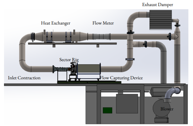
The high-speed wind tunnel is able to deliver mass flows and pressures suitable for reproducing engine-relevant flow conditions in terms of Mach number. The image below illustrates a schematic piping layout for the facility. The air is pressurized by a six-stage centrifugal blower; the blower is driven by a 690 V, 400 kW induction motor and is equipped with an inlet filter. The motor speed is controlled by a variable-frequency drive.
The pressure side of the blower connects to the wind tunnel piping network; the air is first routed vertically upward to a bypass valve connected to the exhaust damper. The main line then proceeds through the test hall and connects to a mass flow measurement device and a heat exchanger. The air is subsequently routed to the test section via two 90° bends. Honeycomb screens are installed after the second bend to provide flow straightening.
After the test section, the air can be routed through the exhaust damper and discharged for open-loop operation, or recirculated through additional piping for closed-loop operation. Temperature and pressure are monitored at several locations within the piping, and vibration monitoring is installed for the blower. The rig is modular and can be reconfigured to accommodate different duct geometries.