Optical sensing on reflective, transparent or untextured surfaces is difficult. Active illumination and computational photography may help in many aspects of industrial computer vision and 3D reconstruction. In the robot vision group we continuously evaluate and apply problem-specific sensing principles to difficult tasks.
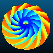
Structured Light Sensing
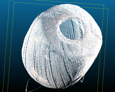
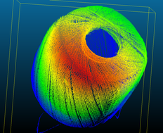
Applying a time-multiplexed projection pattern allows for rapid and robust measurements on complex objects. With state of the art camera and projector hardware we allow for an image acquisition up to 150 frames per second, and 4M 3D points per measurement. A flexible sensor carrier allows to adapt for various baselines and measurement ranges from 50x50mm up to 5000x5000mm. GPU-based code extraction, matching and triangulation allows for rapid results.
The resolution reachable by this sensing principle allows for reliable measurements on a per-pixel level. Even thin and delicate structures are observed and reconstructed.
Time-Multiplexed HDR
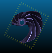
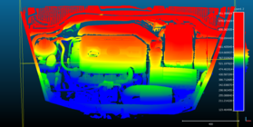
A problem arising on most specular and white surfaces is over-exposure due to reflection. If one and the same scenery contains very dark structures and highly reflective structures, even a dynamic camera range of 12 bit may not capture the dynamic range entirely. One may compensate for this effect by generating exposure sequences and finally merging images of varying exposure into a high-dynamic-range (HDR) image. This comes at the cost of more images to capture, but is still feasible with a fast camera system.
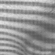
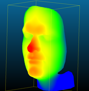
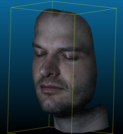
Space-Multiplexed HDR
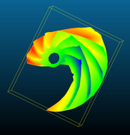
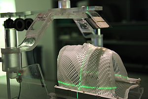
Instead of gaining dynamic range in the temporal domain, one may do so in the spatial domain. By applying intensity filters with varying absorption rate on a per-pixel level, we capture radiometrically complex scenes with a considerably lower number of images, hence increasing the measurement rate for slightly moving objects like faces.
Data Fusion
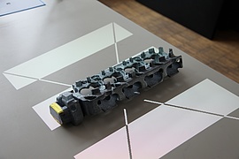
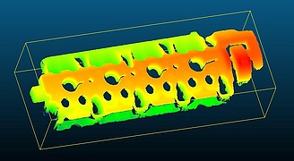
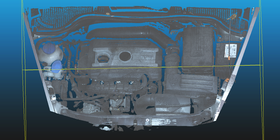
A single point scan delivers measurements only from a given viewpoint. To create 360 degree measurements, and measurements of large objects like an engine block, we estimate the relative sensor motion through structure and motion techniques and finally fuse individual measurements to a complete object.
Robot Vision
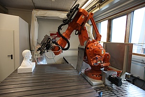
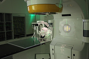
By mounting the sensor on a robot arm and calibrating the kinematic chain, we create a measurement system with several meters of measurement range. This allows us to fully automatically scan large objects.


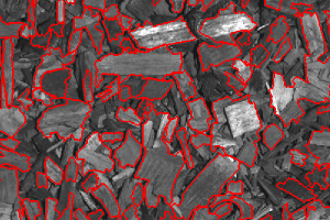
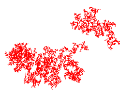
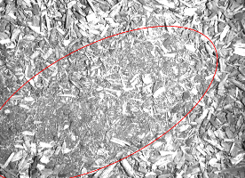
 In the various steps from wood chip production until delivery to the fuel depot of the heating plant unnoticed contamination with foreign particles may occur. Again, these particles pose a threat of obstructing the feeder screw or the grate in the furnace, leading to unexpected plant shutdown. Employing an abnormal event detection framework with sparse dictionary learning methods, foreign matter on the surface of the fuel pile is detected and allows for an automatic removal from the fuel depot.
Contact: Ludwig Mohr, Matthias Rüther
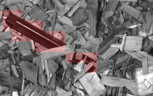
In the various steps from wood chip production until delivery to the fuel depot of the heating plant unnoticed contamination with foreign particles may occur. Again, these particles pose a threat of obstructing the feeder screw or the grate in the furnace, leading to unexpected plant shutdown. Employing an abnormal event detection framework with sparse dictionary learning methods, foreign matter on the surface of the fuel pile is detected and allows for an automatic removal from the fuel depot.
Contact: Ludwig Mohr, Matthias Rüther
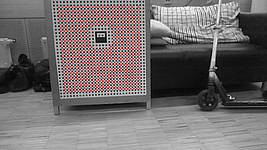
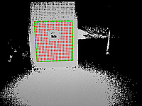
 Our automatic feature detection starts by searching for the central marker and then iteratively refining the circular markers around the central marker (depticted as black dashed line). Compared to standard checkerboard targets, our methods has the following advantages: