Fuel Cells – Materials and Methods for Prolonging Lifetime
The research at the Institute of Chemical Engineering and Environmental Technology focusses on the development of highly innovative materials and efficient operation strategies for fuel cells.
New technologies for emission-free energy conversion are needed in the face of the tug of war between environmental protection and the temptations of the consumer world – especially when it comes to electrical and entertainment technology and transport. Fuel cells enable sustainable electrical power generation for mobile, portable and stationary applications. In the case of transport applications, consumers expect the same ranges and speed of refuelling as they get from conventional mid-size vehicles. Long-lasting, active and stable catalyst systems and innovative operation strategies with very low performance losses are required to guarantee the successful commercialisation of fuel cell systems.
Catalysis in fuel cells
By combining hydrogen and atmospheric oxygen, chemical energy is directly converted to electrical energy via an electrochemical redox reaction. The materials currently used for catalysis, carbon and platinum, reach extremely high reaction rates for the hydrogen oxidation reaction at the anode and the oxygen reduction reaction at the cathode; kinetically ingenious but thermodynamically instable and too costly over the long term.
New approaches to chemical functionalisation of the catalysts with conducting polymers simultaneously result in the desired increase of mass activity and the stabilisation of the catalysts. In such a catalyst system, reactive platinum nanoparticles are embedded in a polymer layer which selectively coats the carbon support. The polymer film protects the catalyst against the corrosive environment in the fuel cell, while the polymer structure changes electronic properties of the components, enhancing the reaction rates for catalysis.
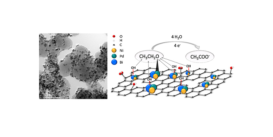
Alternative methods to boost reaction rates and stability are the modification of the carrier material and the establishment of alloys in optimal atomic compositions. Graphene has proven to be a promising carrier material, especially because of its unique structural properties. Innovative ternary catalyst systems based on palladium, nickel and bismuth, with a significant increase in mass activity, have been synthesised for direct ethanol fuel cells.
New catalysts are primarily characterised ex-situ, i.e. outside the normal operating fuel cell. A few micrograms of the prepared catalyst ink are placed on a rotating disk electrode and the mass activity and stability are analysed in half-cell measurements. If the catalyst shows promising characteristics, electrodes are manufactured and tested in-situ for performance and lifetime analysis in fuel cells. The development of new catalysts for energy conversion processes, in which multiple electrons are transferred, are particularly challenging. Disadvantageous intermediate steps and products occurring during the catalysis must be avoided, and material availability, durability, high mass activity and good scalability of the production methods are crucial parameters which have to be observed during catalyst synthesis.

Figure 2: Polarisation and power curve of a 25cm2 PEM fuel cell operated with hydrogen and air.
Degradation of fuel cells
For mobility applications, a lifetime of 5-10 thousand operating hours must be reached in order to achieve market success. Degradation phenomena which occur during real operation are the limiting factors standing in the way of reaching this target. The rapid current variations under dynamic operating conditions, like in a car, lead to mechanical and chemical degradation of materials due to fluctuations in humidity (water management), voltage, temperature and gas distribution, which eventually result in fuel cell conversion efficiencies which are too low.
The development of satisfactory operating strategies requires an understanding of the fundamental processes in the fuel cell, the electrodes, the membrane, the gas diffusion layers, as well as an understanding of the effects of different operating parameters on local performance. Using carefully designed accelerated stress tests (ASTs), the cell is operated under high load conditions to speed up degradation effects such as membrane thinning, carbon corrosion and platinum agglomeration.
During the experiments, the fuel cells are monitored using electrochemical methods including cyclic voltammetry (CV), electrochemical impedance spectroscopy (EIS) and determination of voltage drop using polarisation curves to specify catalyst plus membrane degradation, current plus voltage characteristics, and performance losses. Structural changes to the electrodes and the membrane are identified by means of electron microscopy. Changes in chemical compositions are investigated using X-ray analysis.

Figure 3: SEM image of an electrode layer, identifying platinum agglomeration in specific areas with EDX for elemental composition analysis.
In-situ online monitoring techniques enable new and deeper insights into the degradation mechanisms by means of the visualisation of several performance parameters during the stress tests. Based on the available data from CV, EIS and polarisation curves, a dynamic large signal equivalent circuit (dLSEC) has been developed. With this new diagnostic tool, fast identification and interpretation of performance losses is now possible and the transient behaviour of a fuel cell under certain harmful operating conditions can be simulated. In addition to the simulation, the total harmonic distortion (THD) is used as an important online monitoring method during cell operation to identify harmful operating conditions which occur. The THD uses a superimposed alternating current signal, which becomes distorted if the local operating point moves into the non-linear region of the polarisation curve. These online monitoring techniques have proven to be a valuable tool for enhancing operating strategies for low temperature fuel cells.

Figure 4/1: Schematic illustration of the ternary catalyst system and TEM image of platinum distributed on carbon.example of a dLSEC that is used for fitting data: Rel simulates the voltage loss; the parallel circuits describe charge transfer losses and mass transport losses.

Figure 4/2: Schematic illustration of the ternary catalyst system and TEM image of platinum distributed on carbon. THD peaks at characteristic frequencies in the non-linear region of the polarisation curve.


