Geomagnetically induced currents
Geomagnetically Induced Currents (GICs)
Transformer neutral point currents with frequencies close to 0 Hz, i.e. quasi-direct currents are caused, for example, by changes in the Earth's magnetic field (GICs) or by direct current systems. These low-frequency currents (LFCs) are undesirable in high-voltage transmission grids. They can lead to failures of transformers and thus of the entire grid. The objectives of this research project are:
- Investigation of the influence of low-frequency currents on transformers
- Reduction of the effects of low-frequency currents in the transmission grid
- Calculation of low-frequency currents in the transmission grid
- Transformer neutral point measurement system
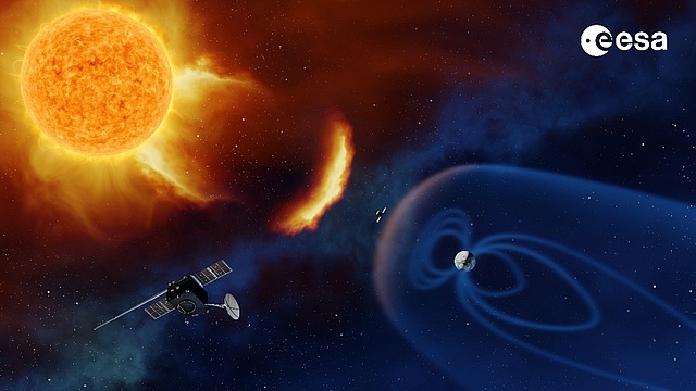
Figure 1: Schematic representation of the influence of a solar storm on the Earth's magnetic field
Transformer neutral point measurement system
The transformer neutral point measurement system is an independent measurement system that can be controlled remotely. A zero-flux current sensor or Hall-effect sensor is used as the current sensor. The neutral point current is sampled at 1 Hz, filtered by an active low-pass filter, and recorded by a single-board computer. With the current configuration of the measurement electronics, neutral point currents with an amplitude of up to 50 A and both polarities can be measured. In addition, three further voltage measurement channels are available, which are also recorded at a sampling rate of 1 second. In Austria, the transformer neutral point current is currently being measured and recorded at nine positions, and there is also a measuring station in the German transmission grid.
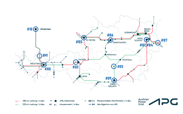
Figure 2: Overview of the GIC measurement system in the APG transmission grid
 |
 |
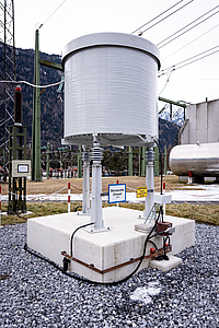 |
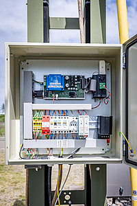
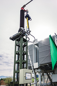
Figure 3: GIC measurement system mounted on grounding arm and neutral point choke
However, geomagnetic storms not only cause direct currents in the transmission grid, but can also trigger auroras during stronger space weather events, which are even visible in Central Europe. As can be seen in the following graphic (Picture 4), this was also the case during the Mother's Day storm in Carinthia in May 2024.
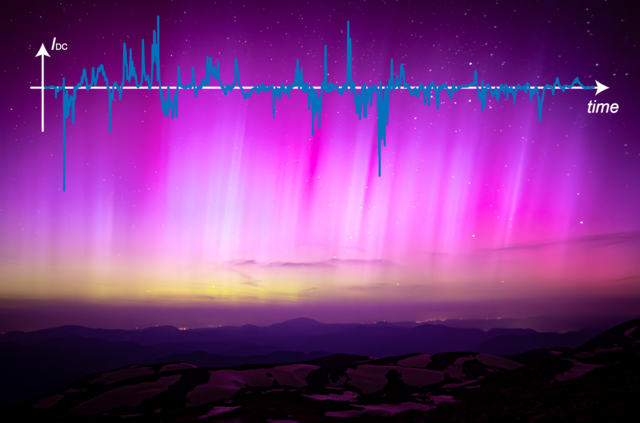
Figure 4: Northern lights over Austria during the Mother's Day storm in 2024 with GIC waveform at a measuring station
GIC Simulation Tool
To accurately predict GICs, a special simulation tool is also being developed that calculates GICs in the power grid based on the electric field and grid configuration. The electric field can either be determined from magnetic field measurements or entered directly into the tool. The plane wave method in conjunction with a 1D earth conductivity model is used for calculations based on magnetic field measurements.
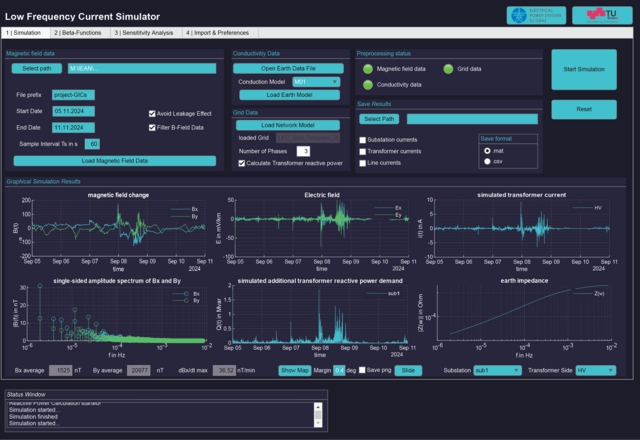
Figure 5: GIC simulation tool
|
|
|
|