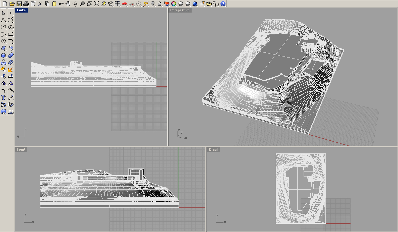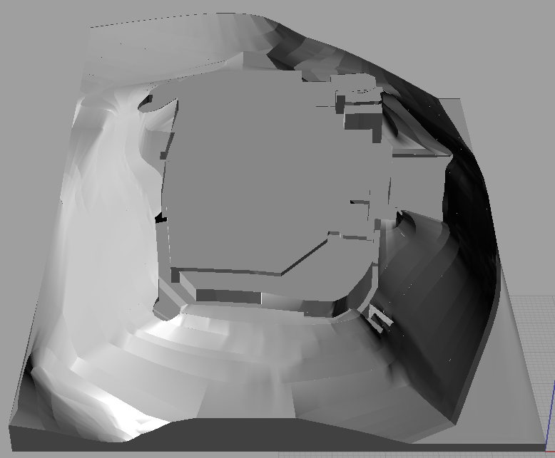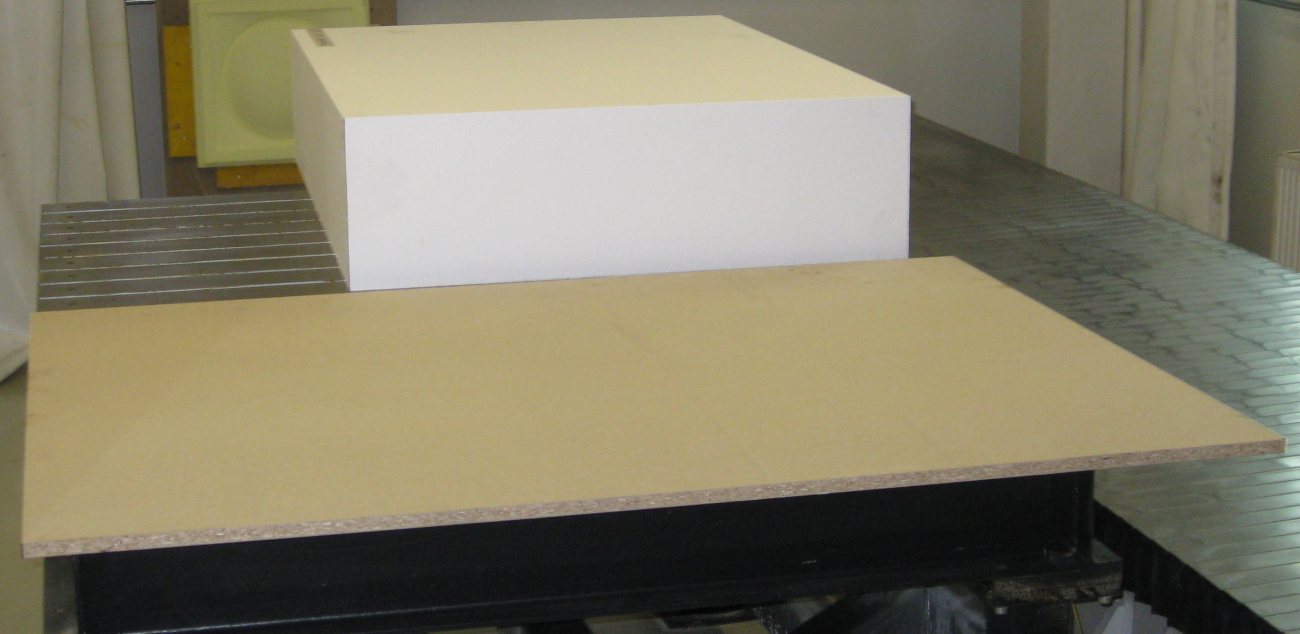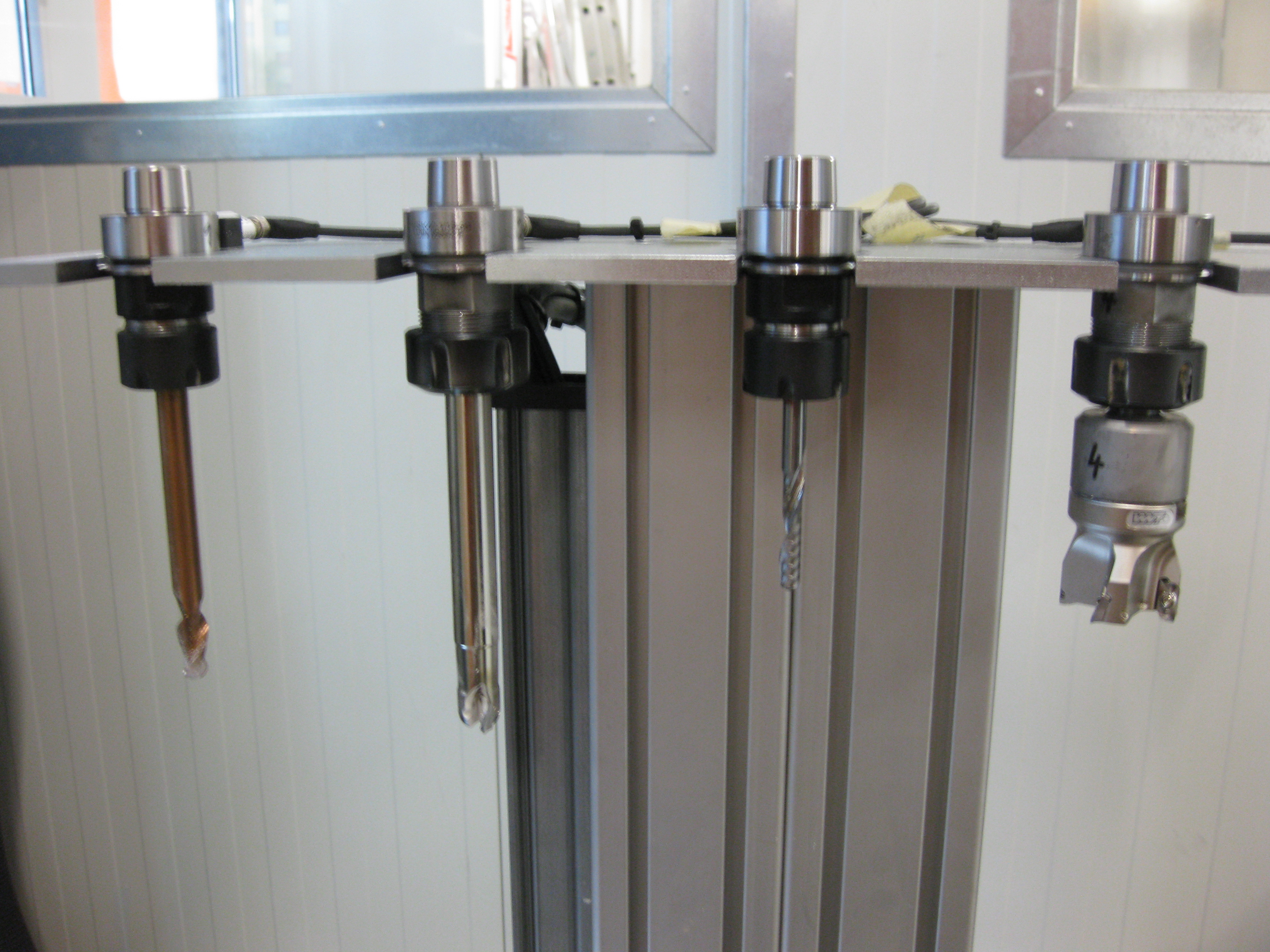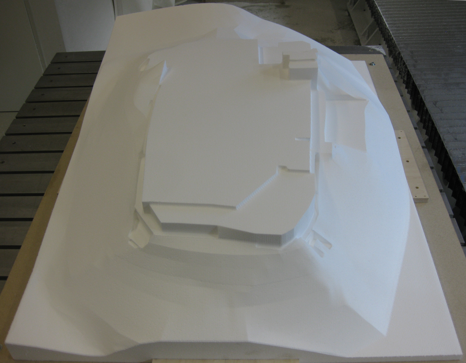
Process
Example: Processing steps for a milling model
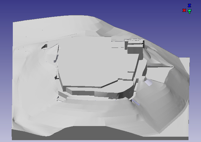
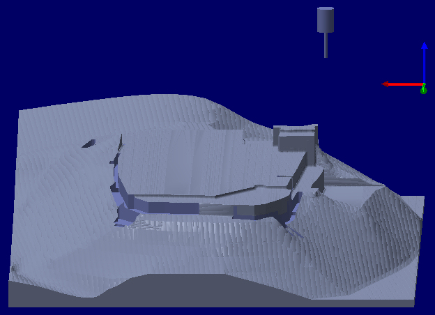
It is essential to consider the requirements of the milling process from the very beginning (design of the component and drawing of CAD file).
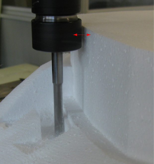
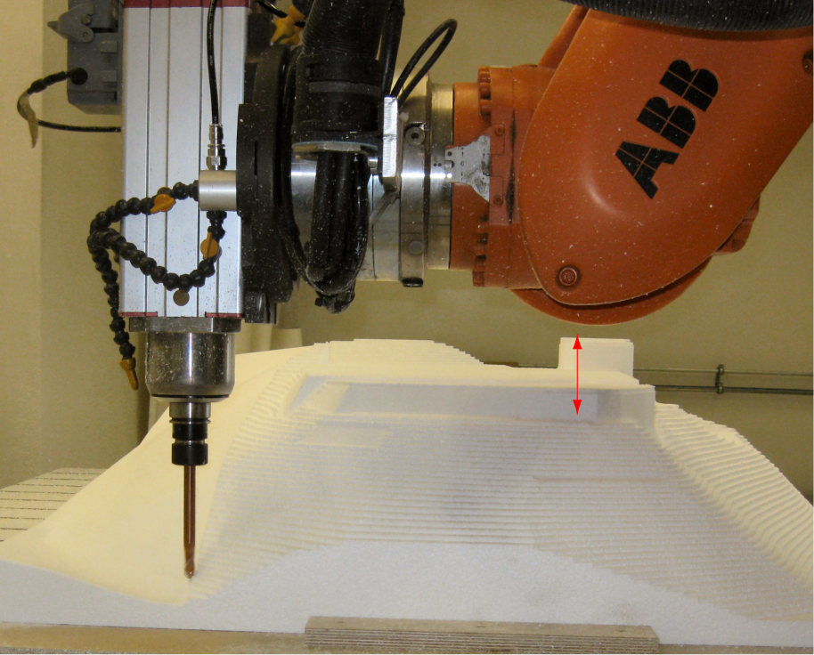
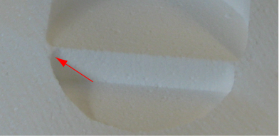
For example it has to be taken into considered that no sharped-edge inner corners can be manufactured. The radius of the inner corners is in general linked to the drill radius.
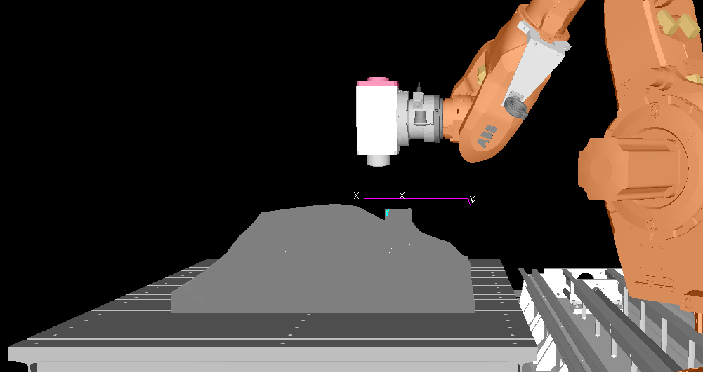
At the same time, possible collisions with the tool fittings, such as the spindle housing and the robot arm, have to be checked and avoided.