Converting Real Objects to Mathematical Models for Design and Simulation

The goal of this research was to make it easier to produce computerised models from real world models. Often, when designing products, a designer starts by making a real world model of their idea, i.e. a clay model. These models are then digitized, for example by using a laser scanner. The point clouds created in the scanning process are typically very dense, they can be visualized on a computer screen but they are too dense for further modification on the computer. For the designer to be able to manipulate the data sensibly and in a controlled manner the number of data points have to be reduced. Only a coarse mesh allows the efficient later manipulation of the model on a computer. Also, the model needs to enter into a larger modelling pipeline, which requires the scan data to be converted to a mathematical representation of the shape, i.e. to a standard CAD representation like subdivision or NURBS surfaces. Both these surface representations offer the designer a control polyhedron as a manipulation interface, which is mathematically linked to a smooth limit surface describing the shape. Ideally, the control mesh is very sparse, so that the shape described by the smooth limit surface can be controlled by moving just a few points of the control mesh. In this project we explored several ways to ease the conversion from a dense point cloud to a coarse mathematical representation of the shape, so a designer can transition easily between designing in the real world and/or manipulating his/her design on the computer. Deriving a Subdivision Control Mesh There exist a number of algorithms to convert scan data to quad meshes. We evaluated some of those as a basis to derive good subdivision control meshes. To simply apply inverse subdivision to these meshes to derive a control polygon will lead to highly irregular control meshes. Although the limit surface of those control meshes lie on the scan data, they cannot be used for further manipulation due to their irregularity. We used normal information to simply pull the vertices up and adjusted their height, so that the limit point related to the control point meets the scan data as close as possible.  Publication: Procedural Mesh Features Applied to Subdivision Surfaces using Graph Grammars, Thaller, W., Augsdörfer, U., Fellner, D. W.; in Computers & Graphics, 56, p. 184-192
From scan data provided (left) we defined a Catmull-Clark control mesh (2nd from left). The corresponding limit surface (3rd from left) approximates closely the input scan data. The error between the Catmull-Clark limit surface and the scan data is shown in the last Figure.
Adding Detail to Coarse Control Meshes Often, details visible in the scan are not required in the mathematical model, since designers often need control over feature placement. A typical industrial design modelling scenario involves defining the overall shape of a product followed by adding detail features. When converting scans to subdivision control meshes we can extract very coarse subdivision base meshes by ignoring any detail of the shape. To then enable the designer to quickly add detail to coarse meshes we have developed a prototype system which automatically changes the topology of a subdivision control mesh to apply various pre-defined surface features with only a small increase in resolution to achieve good visual properties. A large amount of expert knowledge is applied when adding features to control meshes. Changes to the topology of the control mesh may give rise to artefacts in the limit surface. To apply free-form design features to a subdivision surface, a CAD expert meticulously adjusts the resolution and the mesh topology of the subdivision control mesh in order to keep changes to the overall shape small and to avoid or hide the visual appearance of artefacts. Once a good topology change is identified, the expert applies the same procedure each time the same or a similar feature has to be applied. To capture this expert knowledge so a surface feature may be applied by a non-expert and may be applied repeatedly without additional effort we employed graph grammars. Changing the topology of a mesh may give rise to artefacts in the nearby msh region. Surrounding control vertices are adjusted to minimise changes in the surface surrounding the feature.    Publication: Procedural Mesh Features Applied to Subdivision Surfaces using Graph Grammars, Thaller, W., Augsdörfer, U., Fellner, D. W.; in Computers & Graphics, 56, p. 184-192
Topology changes to incorporate a groove-feature into a subdivision surface control mesh: The designer marks the affected edges in the control mesh and the system automatically applies a chain of rules to each marked edge to add a
Deriving Curvature Sensitive Subdivision Control Meshes Deriving quad meshes from scan data which contain features, that is regions of high curvature, typically results in highly dense meshes which match the scan data with good accuracy but contain many superfluous vertices. Alternatively, if the quad mesh generated from the scan data is sparse it approximates the scan data with low accuracy in regions which contain detailed features. We extended an existing algorithm by Jakob et al. by adjusting the density of the mesh with respect to curvature. We extract meshes which are highly non-isotropic and which approximate the surface with the same user defined accuracy everywhere. In this way we can create control meshes with fewer points, but which can retain more detail information.
On the left is the surface resulting from scan capture. 2nd from left: The subdivision control mesh generated from the scan data. The limit surface derived from control mesh is shown (3rd from left) before colorizing the error between the scan data and limit surface (right). Top row: The control mesh is dense in regions where it is required to capture fine detail, but coarse in regions of low curvature. The resulting limit surface shows a lot more detail when compared to the bottom row, which extracted a quad mesh with the same number of vertices than the at the top, but where the distribution is more isotropic. As a result the limit surface corresponding to this control mesh contains considerably less detail and the error to the scan data is larger.
Matching Scan Data to existing CAD Models Instead of extracting a mathematical representation from scan data, we may match a real life object to its corresponding CAD model. The CAD model can then be used for re-manufacture of this part, or used as a basis for further modification to fit new requirements. If an exact match does not exist we may want to match a CAD model which comes as close as possible to the real world part. This model could then be used as a basis for further manipulation and it would save the designer having to CAD design the model from scratch. To ease the CAD data retrieval we developed a 3D object retrieval chain which uses the Hololense. The user simply looks at the real world object from which the Hololense automatically takes a number of pictures as the user moves around the object. Based on the pictures a point cloud of the object is determined. The resulting point cloud is used to retrieve the best fit CAD model from a CAD large data bank to match the scan data with its corresponding mathematical description. The CAD model is either an exact match or the closest match to the scan data. The CAD model is then overlaid with the real world object and visible to the user. Any differences between the real world object and the CAD model may be highlighted to make them obvious to the designer, who may wish to introduce chances to the CAD model to more closely fit the existing real world model.
Left: The user simply looks at the real world object, here, a tablet. The Hololense automatically takes 6 pictures which are used to derive a point cloud of the object. The point cloud is used to compare the 3D shape to a large CAD data bank from which the corresponding CAD model is retrieved and overlaid with the point cloud (centre). The user can choose to look at the CAD model only, which is presented to the user in exact the same position as the real object.
Conversion for Analysis If we envisage a new purpose for an existing object, it were useful if we had a way to check whether the existing object is suitable for this new purpose. To do so, the object is digitized, assigned material properties and then undergoes a thorough finite element analysis. Similarly, we may want to change the shape of an existing object and use it for a similar purpose, i.e. increase the size of a vase and still be able to manufacture it and use it as a vase. For such a scenario it is useful to determine a mathematical representation which enables both, design and analysis. Since the trend in product design goes toward finding a way of combining the design of aesthetics and functionally aspects of the product we would like to determine a mathematical representation from the scan data which is useful for CAD and finite element analysis. We have previously analysed the requirements for subdivision control meshes to be suitable for what is referred to as isogeometric analysis. As part of this project we have focused in particular on identifying problems which may arise for certain mesh structures. Artifacts contained in the analysis results due to the structure of the mesh or a lack in mesh quality may make an interpretation of the results difficult or even render the results useless. The research of this project aimed at finding a mathematical representation where the resultant data is extremely coarse. However, if we would like the representation to also be useful for analysis we need enough degrees of freedom to be able to adequately represent the solution of the analysis. Another source of artifacts are shape imperfections in the geometry introduce due to scanning inaccuracies. These imperfection may e.g. appear as weak spots in the shape's structural stability and introduce predetermined breaking points. Also, mesh structure is important. In CAD design features running skew to mesh grid lines are known to be sources of artifacts and are therefore avoided by the designer. During analysis, features may appear skew to the grid lines due to the effect of forces acting on the shape. The artefacts this heralds will be visible as ripples in the resulting surface and are not part of the solution space. This problem can in parts be circumvented by matching the scan data to the intended CAD design, and then employing the CAD model for analysis. To prevent artefacts occuring due to grid lines running skew to a feature appearing in analysis we are investigating two ways: To re-mesh the geometry in order to prevent these problems the type and direction of forces which are expected to act on the shape need to be estimated or indicated by the user. Else, by automatically identifying features and their direction in relation to the underlying mesh structure, we may be able to identify and eliminate artefacts in the simulation results. 
Flat plane subject to uniform upward force. Top: with a rotated grid. Bottom: with aligned grid; Vertices/Edges marked in red in the control grid are fixed in place. Actual displacement has been amplified by a factor of 10 for better visibility of the artefacts. The diagonal grid leads to severe artefacts visible throughout the displaced geometry. For high resolution meshes (initial grid subdivided three times; bottom two rows) both input meshes produce approximately the same result without large artefacts.

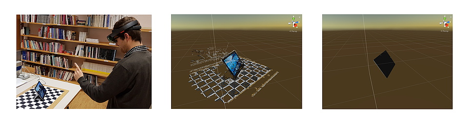
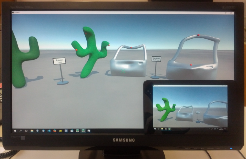
Real Objects in Virtual Reality

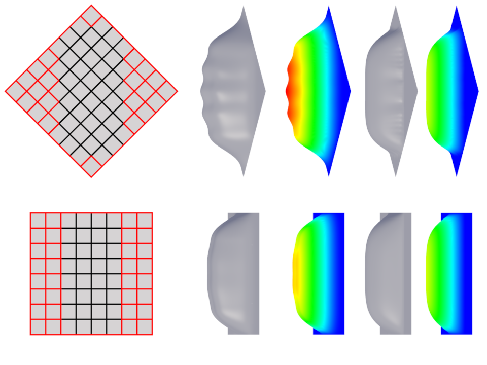
Virtual environments (VR) are used more and more to depict digitised artefacts of various kinds. Users are able to visit everything from virtual museums where scanned in versions of real artefacs are displayed, to entire buildings from the comfort of their living room. The advantage here is that not only does it not require any time consuming travel, it also enables the viewer to get very close to objects, which may otherwise not be possible and also to interact with objects where it may not be possible in the real world scenario. Thus, when we want take full advantage of VR, we should aim toward creating immersive interactive virtual worlds which not only provide plausible visuals, but also allow the user to interact with artefacts and the visual scene in a natural way. While rigid-body physics simulations are widely used to provide basic interaction, realistic soft-body deformations of virtual objects are challenging and therefore typically not offered. However, in the real world we are used to interacting with things, e.g. to assess material properties of an object upon how it responds to interaction. Therefore, having only rigid objects in VR reduces immersion since many real world objects are easily deformed. To enable users to interact with an artefact in a plausible way, so that response of the artefacts to this interaction may help to assess material properties, the response of the objects needs to simulate accurate physical behaviour which is typically determined through a detailed finite element analysis of the object.

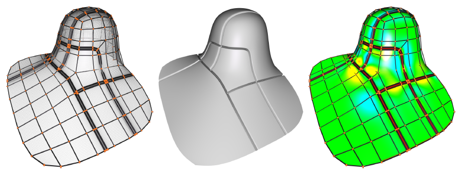
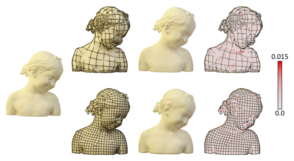
To enable realistic interaction with objects in VR environments on a range of devices with various capabilities, we propose a client-server approach which makes use of subdivision based isogeometric analysis. This requires to convert the highly detailed scan of the real object to be converted to a coarse subdivision control mesh. Deformations are computed on a central server and results are available to multiple clients. By using subdivision surfaces to represent the geometry and to perform the simulation computations, bandwidth usage is kept low and different clients can easily render different levels of detail according to their capabilities.

The project was made possible by the FWF Wissenschaftsfond, Project Nr. E-1711P24481.

Research staff involved in the project
image/svg+xml
Ursula Augsdörfer
Assoc.Prof. M.Sc. PhD
Tel.
+43 316 873 - 5414
Fax
+43 316 873 - 105414