
How FlyGrid works...
The figure below shows a simplified circuit diagram of the FlyGrid system. The heart of the idea is the flywheel energy storage device, consisting of a spinning mass (rotor) connected to a high efficient motor-generator as described in figure 2. The power inverter, which controls the electric machine of the FESS is connected to a DC voltage link. Power can be fed from the grid into the flywheel, through an AC/DC converter (plus power factor controller), or directly to the EV if desired. On the “vehicle side” of the system, custom power electronics allows either DC or AC charging, depending on the capabilities of the vehicle. The high charging power peaks are supplied by the FESS and – depending on the configuration of the motor generator – could reach values of several hundred kW! The current is transmitted to the vehicle via the fully automated, innovative MATRIX CHARGING® system by easelink, which was invented (and is still being developed) in Austria.
While the Austrian electricity mix has a significant share of renewables (~70 %) due to the abundancy of hydro power, this is not the case in other countries. FlyGrid allows the integration of highly volatile local renewables (wind, solar) etc. for instance by using the roofs of carports for PV installation. To avoid transmission and power conversion losses, the local renewable electricity can be fed directly into the DV voltage link of the flywheel and either be stored for later use or routed to the EV for immediate charging.
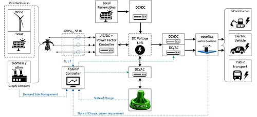
Figure 1: Schematics of the FlyGrid system from grid to vehicle.
The FlyGrid system is governed by a high-level controller, which receives information from the following modules: · Electric vehicle: AC vs. DC charging type, state of charge, power demand etc. · Flywheel: State of charge, state of health · Electric grid: Voltage, current and frequency · Electricity supplier: Demand side management commands With this information the controller can operate the system in such way that grid loads are minimized and renewables are used in the most efficient way.| Another benefit is that - if the electricity supplier demands it - the FESS can either feed power back into the grid or be charged when excess energy is available. The ultra-fast reaction time of the flywheel power electronics (~milliseconds) allows nearly instantaneous compensation when the grid frequency drops, which can be crucial for avoiding blackouts. |
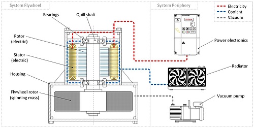
Figure 2: Electromechanical Flywheel Energy Storage System
Enhanced grid stability and power quality through the introduction of inertia in the grid are positive side-effects of FlyGrid. One may argue that with only limited power available to charge up the FESS, it would take long to recharge after the flywheel has spun down during the EV charging cycle. While this is true to a certain extent, it must be mentioned that the EV charge power is only at its maximum at the very beginning of the charge cycle (“constant current mode”) and then drops (“constant voltage mode”) until it reaches “trickle charging” during the last 5 ~15 % of the EV battery’s state of charge. From this, three important conclusions can be drawn: a) The actual energy content that must be stored in the FESS is much lower than the energy content of the EV battery b) The FESS can be charged up again, even when the EV is still plugged in by using the excess power between trickle charging and maximum available grid power c) As a consequence of b), the load on the grid will be completely uniform!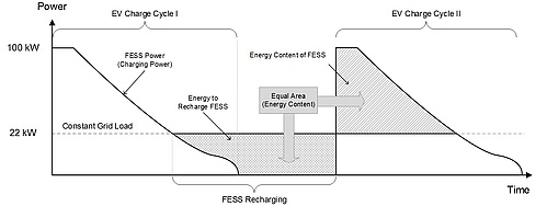
Figure 3: Charging cycle of a FlyGrid facility in a low power distributor grid.